A codec is a device or computer program for encoding or decoding a digital data stream or signal. Codec is a portmanteau of coder-decoder. A codec encodes a data stream or a signal for transmission and storage, possibly in encrypted form, and the decoder function reverses the encoding for playback or editing. Below you will see a table of all Codec types with IDs:
Also, there are using two data transport protocols: TCP and UDP. But it is not important which one will be used in Codec.
In this chapter, you will find information about every Codec protocol which are used for device data sending and the differences between them.
Codec8 – a main FM device protocol that is used for sending data to the server.
TCP is a connection-oriented protocol that is used for communication between devices. The workings of this type of protocol is described below in the communication with server section.
The below table represents the AVL Data Packet structure:
Preamble – the packet starts with four zero bytes. Data Field Length – size is calculated starting from Codec ID to Number of Data 2. Codec ID – in Codec8 it is always 0x08 . Number of Data 1 – a number that defines how many records are in the packet. AVL Data – actual data in the packet (more information below). Number of Data 2 – a number that defines how many records are in the packet. This number must be the same as “Number of Data 1”. CRC-16 – calculated from Codec ID to the Second Number of Data. CRC (Cyclic Redundancy Check) is an error-detecting code used to detect accidental changes to RAW data. For calculation we are using CRC-16/IBM . Note: for FMB640 , FMB641 , FMC640 , and FMM640 , minimum AVL record size is 45 bytes (all IO elements disabled). The maximum AVL record size is 255 bytes. Maximum AVL packet size is 512 bytes. For other devices, the minimum AVL record size is 45 bytes (all IO elements disabled). Maximum AVL packet size is 1280 bytes.
The below table represents the AVL Data structure.
Timestamp – a difference, in milliseconds, between the current time and midnight, January 1970 UTC (UNIX time). Priority – a field that defines AVL data priority (more information below). GPS Element – location information of the AVL data (more information below). IO Element – additional configurable information from the device (more information below).
The below table represents Priority values. Packet priority depends on device configuration and records sent.
The below table represents the GPS Element structure:
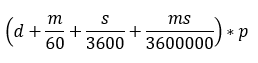
Longitude – east-west position. Latitude – north-south position. Altitude – meters above sea level. Angle – degrees from north pole. Satellites – number of satellites in use. Speed – speed calculated from satellites. Note: Speed will be 0x0000 if GPS data is invalid. Longitude and latitude are integer values built from degrees, minutes, seconds, and milliseconds by the formula: Where: d – Degrees; m – Minutes; s – Seconds; ms – Milliseconds; p – Precision (10000000) If the longitude is in the west or latitude in the south, multiply the result by –1. Note: To determine if the coordinate is negative, convert it to binary format and check the very first bit. If it is 0, the coordinate is positive. If it is 1, the coordinate is negative. Example: Received value: 20 9C CA 80 converted to BIN: 00100000 10011100 11001010 10000000 first bit is 0, which means coordinate is positive converted to DEC: 547146368 . For more information see two‘s complement arithmetic.
N – a total number of properties coming with record (N = N1 + N2 + N4 + N8). N1 – number of properties, which length is 1 byte. N2 – number of properties, which length is 2 bytes. N4 – number of properties, which length is 4 bytes. N8 – number of properties, which length is 8 bytes. N’th IO ID - AVL ID. N’th IO Value - AVL ID value.
First, when the module connects to the server, the module sends its IMEI. First comes a short identifying the number of bytes written and then goes IMEI as text (bytes). For example, IMEI 356307042441013 would be sent as 000F333536333037303432343431303133 . The first two bytes denote IMEI length. In this case 0x000F means, that IMEI is 15 bytes long. After receiving IMEI, the server should determine if it would accept data from this module. If yes, server will reply to module 01 , if not - 00 . Note that confirmation should be sent as a binary packet. I.e. 1 byte 0x01 or 0x00 . Then the module starts to send the first AVL data packet. After the server receives a packet and parses it, the server must report to the module number of data received as an integer (four bytes). If the sent data number and the reported by the server don’t match module resends the sent data.
The module connects to the server and sends IMEI: 000F333536333037303432343431303133 The server accepts the module: 01 The module sends data packet:
“AVL Data Array” length – 0x000000FE
Number of Data – 0x02 (Encoded using continuous bit stream. The last byte is padded to align to the byte boundary)
Server acknowledges data reception (2 data elements): 00000002
The hexadecimal stream of AVL Data Packet receiving and response in these examples are given in the hexadecimal form. The different fields of packets are separated into different table columns for better readability and some of them are converted to ASCII values for better understanding.
1'st example Receiving one data record with each element property (1 byte, 2 bytes, 4 bytes, and 8 bytes). Received data in the hexadecimal stream: 000000000000003608010000016B40D8EA30010000000000000000000000000000000105021503010101425E0F01F10000601A014E0000000000000000010000C7CF Parsed:
Server response: 00000001
2'nd example Receiving one data record with one or two different element properties (1 byte, 2 bytes). Received data in the hexadecimal stream: 000000000000002808010000016B40D9AD80010000000000000000000000000000000103021503010101425E100000010000F22A Parsed:
3'rd example Receiving two or more data records with one or more different element properties. Received data in the hexadecimal stream: 000000000000004308020000016B40D57B480100000000000000000000000000000001010101000000000000016B40D5C198010000000000000000000000000000000 101010101000000020000252C Parsed:
Server response: 00000002
Codec8 protocol [over UDP] is a transport layer protocol above UDP/IP to add reliability to plain UDP/IP using acknowledgment packets.
The packet structure is as follows:
Example – packet length (excluding this field) in big ending byte order. Packet ID – packet ID unique for this channel. Not Usable Byte – not usable byte. Packet payload – data payload.
The acknowledgment packet should have the same Packet ID as an acknowledged data packet and empty Data Payload. Acknowledgment should be sent in binary format.
Packet Length – packet length by sending/response data. Packet ID – same as in acknowledgment packet. Not Usable Byte – always will be 0x01 .
The below table represents the Sending Packet Payload structure.
AVL Packet ID – ID identifying this AVL packet. IMEI Length – always will be 0x000F . Module IMEI – IMEI of a sending module encoded the same as with TCP. AVL Data Array – an array of encoded AVL data (same as TCP AVL Data Array).
The below table represents the Server Response Packet Payload structure.
The module sends the UDP channel packet with an encapsulated AVL data packet. The server sends the UDP channel packet with an encapsulated response module that validates the AVL Packet ID and the Number of accepted AVL elements. If the server response is not received with a valid AVL Packet ID within configured timeout, the module can retry sending.
The module sends the data:
Packet ID – 0xCAFE Not Usable Byte – 0x01
IMEI Length – 0x000F IMEI – 0x313233343536373839303132333435 (Encoded using continuous bit stream. The last byte is padded to align to the byte boundary)
Number of Data – 0x02 (Encoded using continuous bit stream)
The server must respond with an acknowledgment:
Packet ID – 0xCAFE, Not Usable Byte – 0x01
Number of Accepted Data – 0x02
The hexadecimal stream of AVL Data Packet receiving and response in this example is given in the hexadecimal form. The different fields of the packet are separated into different table columns for better readability and some of them are converted to ASCII values for better understanding. Received data in the hexadecimal stream: 003DCAFE0105000F33353230393330383634303336353508010000016B4F815B30010000000000000000000000000000000103021503010101425DBC000001 Parsed:
The server response in the hexadecimal stream: 0005CAFE010501 Parsed:
Codec8 Extended is used for FMBXXX family devices. This protocol looks familiar to Codec8 but they have some differences. The main differences between them are shown in below table:
Preamble – the packet starts with four zero bytes. Data Field Length – size is calculated starting from Codec ID to Number of Data 2. Codec ID – in Codec8 Extended it is always 0x8E . Number of Data 1 – a number that defines how many records are in the packet. AVL Data – actual data in the packet (more information below). Number of Data 2 – a number that defines how many records are in the packet. This number must be the same as “Number of Data 1”. CRC-16 – calculated from Codec ID to the Second Number of Data. CRC (Cyclic Redundancy Check) is an error-detecting code used to detect accidental changes to RAW data. For calculation we are using CRC-16/IBM . Note: for FMB640 , FMB641 , FMC640 , and FMM640 , minimum AVL record size is 45 bytes (all IO elements disabled). The maximum AVL record size is 255 bytes. For other devices, the minimum AVL record size is 45 bytes (all IO elements disabled). Maximum AVL packet size is 1280 bytes.
The below table represents the AVL Data structure:
Timestamp – a difference, in milliseconds, between the current time and midnight, January 1970 UTC (UNIX time). Priority – a field that defines AVL data priority (more information below). GPS Element – locational information of the AVL data (more information below). IO Element – additional configurable information from the device (more information below).
Longitude – east-west position. Latitude – north-south position. Altitude – meters above sea level. Angle – degrees from north pole. Satellites – number of satellites in use. Speed – speed calculated from satellites. Note: Speed will be 0x0000 if GPS data is invalid. Longitude and latitude are integer values built from degrees, minutes, seconds, and milliseconds by the formula: Where: d – Degrees; m – Minutes; s – Seconds; ms – Milliseconds; p – Precision (10000000) If the longitude is in the west or latitude in the south, multiply the result by –1. Note: To determine if the coordinate is negative, convert it to binary format and check the very first bit. If it is 0 , the coordinate is positive, if it is 1 , the coordinate is negative. Example: Received value: 20 9C CA 80 converted to BIN: 00100000 10011100 11001010 10000000 first bit is 0, which means coordinate is positive converted to DEC: 547146368 . For more information see two‘s complement arithmetic.
N – a total number of properties coming with record (N = N1 + N2 + N4 + N8). N1 – number of properties, which length is 1 byte. N2 – number of properties, which length is 2 bytes. N4 – number of properties, which length is 4 bytes. N8 – number of properties, which length is 8 bytes. NX – a number of properties, which length is defined by the length element. N’th IO ID - AVL ID. N'th Lenght - AVL ID value lenght. N’th IO Value - AVL ID value.
Communication with the server is the same as with the Codec8 protocol, except in Codec8 Extended protocol Codec ID is 0x8E.
The hexadecimal stream of AVL Data Packet receiving and response in this example is given in the hexadecimal form. The different fields of the packet are separated into different table columns for better readability and some of them are converted to ASCII values for better understanding. Received data in the hexadecimal stream: 000000000000004A8E010000016B412CEE000100000000000000000000000000000000010005000100010100010011001D00010010015E2C880002000B000000003544C87 A000E000000001DD7E06A00000100002994 Parsed data:
AVL data packet is the same as with Codec8, except Codec ID is changed to 0x8E . AVL Data encoding was performed according to Codec8 Extended protocol.
The hexadecimal stream of AVL Data Packet receiving and response in this example is given in the hexadecimal form. The different fields of the packet are separated into different table columns for better readability and some of them are converted to ASCII values for better understanding. Received data in the hexadecimal stream: 005FCAFE0107000F3335323039333038363430333635358E010000016B4F831C680100000000000000000000000000000000010005000100010100010011009D000100 10015E2C880002000B000000003544C87A000E000000001DD7E06A000001 Parsed:
The server response in the hexadecimal stream: 0005CAFE010701 Parsed:
Codec16 is using for FMB630 /FM63XY series devices. This protocol looks familiar like Codec8 but they have some differences. The main differences between them are shown in the table below:
Note: Codec16 is supported from firmware – 00.03.xx and newer. ( FMB630 /FM63XY) || AVL IDs that are higher than 255 will can be used only in the Codec16 protocol.
Preamble – the packet starts with four zero bytes. Data Field Length – size is calculated starting from Codec ID to Number of Data 2. Codec ID – in Codec16 it is always 0x10. Number of Data 1 – a number that defines how many records are in the packet. AVL Data – actual data in the packet (more information below). Number of Data 2 – a number that defines how many records are in the packet. This number must be the same as “Number of Data 1”. CRC-16 – calculated from Codec ID to the Second Number of Data. CRC (Cyclic Redundancy Check) is an error-detecting code used to detect accidental changes to RAW data. For calculation we are using CRC-16/IBM . Note: for FMB630 and FM63XY, the minimum AVL record size is 45 bytes (all IO elements disabled). The maximum AVL record size is 255 bytes.
Generation type - data event generation type. More information about it you can find here. N – a total number of properties coming with record (N = N1 + N2 + N4 + N8). N1 – number of properties, which length is 1 byte. N2 – number of properties, which length is 2 bytes. N4 – number of properties, which length is 4 bytes. N8 – number of properties, which length is 8 bytes. N’th IO ID - AVL ID. N’th IO Value - AVL ID value.
Communication with the server is the same as with Codec8 protocol, except in Codec16 protocol Codec ID is 0x10 and has generation type.
The hexadecimal stream of AVL Data Packet receiving and response in this example is given in the hexadecimal form. The different fields of the packet are separated into different table columns for better readability and some of them are converted to ASCII values for better understanding. Received data in the hexadecimal stream: 000000000000005F10020000016BDBC7833000000000000000000000000000000000000B05040200010000030002000B00270042563A00000000016BDBC78718 00000000000000000000000000000000000B05040200010000030002000B00260042563A00000200005FB3 Parsed data:
AVL data packet is the same as with Codec8, except Codec ID is changed to 0x10 . AVL Data encoding is performed according to the Codec16 protocol.
The module sends the UDP channel packet with an encapsulated AVL data packet. The server sends the UDP channel packet with an encapsulated response module that validates the AVL Packet ID and the Number of accepted AVL elements. If the server responds with a valid AVL Packet ID that is not received within configured timeout, the module can retry sending.
The hexadecimal stream of AVL Data Packet receiving and response in this example is given in the hexadecimal form. The different fields of the packet are separated into different table columns for better readability and some of them are converted to ASCII values for better understanding. Received data in the hexadecimal stream: 015BCAFE0101000F33353230393430383532333135393210070000015117E40FE80000000000000000000000000000000000EF05050400010000030000B4000 0EF01010042111A000001 Parsed:
In the table below you will see differences between Codec8, Codec8 Extended, and Codec16.
In this chapter, you will find information about every Codec protocol which are used for communication over GPRS messages and the differences between them.
Codec12 is the original and main Teltonika protocol for device-server communication over GPRS messages. Codec12 GPRS commands can be used for sending configuration, debug, digital outputs control commands, or other (special purpose commands on special firmware versions). This protocol is also necessary for using FMB630 / FM6300 /FM5300/FM5500/FM4200 features like Garmin, LCD communication, and COM TCP Link Mode.
The following figure shows how the GRPS command session is started over TCP. First, the Teltonika device opens the GPRS session and sends AVL data to the server (refer to device protocols). Once all records are sent and the correct sent data array acknowledgment is received by the device then GPRS commands in Hex can be sent to the device. The ACK (acknowledgment of IMEI from server) is a one-byte constant 0x01. The acknowledgment of each data array send from the device is four bytes integer – a number of received records. Note, that the GPRS session should remain active between the device and server, while GPRS commands are sent. For this reason, active datalink timeout (global parameters in device configuration) is recommended to be set to 259200 (maximum value).
The following diagram shows the basic structure of Codec12 messages. Command message structure:
Response message structure:
Preamble - the packet starts with four zero bytes. Data Size - size is calculated from the Codec ID field to the second command or response quantity field. Codec ID - in Codec12 it is always 0x0C . Command/Response Quantity 1 - it is ignored when parsing the message. Type - it can be 0x05 to denote command or 0x06 to denote response. Command/Response Size – command or response length. Command/Response – command or response in HEX. Command/Response Quantity 2 - a byte that defines how many records (commands or responses) are in the packet. This byte will not be parsed but it’s recommended that it should contain the same value as Command/Response Quantity 1. CRC-16 – calculated from Codec ID to the Command Quantity 2. CRC (Cyclic Redundancy Check) is an error-detecting code used to detect accidental changes to RAW data. For calculation we are using CRC-16/IBM . Note that the difference between commands and responses is the message type field: 0x05 means command and 0x06 means response.
Command has to be converted from ASCII characters (char) to hexadecimal (HEX):
The hexadecimal stream of command and answer in this example is given in the hexadecimal form. The different fields of the message are separated into different table columns for better readability and understanding.
The hexadecimal stream of GPRS command and answer in these examples are given in the hexadecimal form. The different fields of messages are separated into different table columns for better readability and some of them are converted to ASCII values for better understanding. 1'st example: Sending getinfo SMS command via GPRS Codec12 Server request in the hexadecimal stream: 000000000000000F0C010500000007676574696E666F0100004312 Parsed:
Note that Server Command converted from HEX to ASCII means getinfo Device response in the hexadecimal stream: 00000000000000900C010600000088494E493A323031392F372F323220373A3232205254433A323031392F372F323220373A3533205253543A32204552523A 312053523A302042523A302043463A302046473A3020464C3A302054553A302F302055543A3020534D533A30204E4F4750533A303A3330204750533A312053 41543A302052533A332052463A36352053463A31204D443A30010000C78F Parsed:
Note that Device Response converted from HEX to ASCII means: INI:2019/7/22 7:22 RTC:2019/7/22 7:53 RST:2 ERR:1 SR:0 BR:0 CF:0 FG:0 FL:0 TU:0/0 UT:0 SMS:0 NOGPS:0:30 GPS:1 SAT:0 RS:3 RF:65 SF:1 MD:0
2'nd example: Sending getio SMS command via GPRS Codec12 Server request in the hexadecimal stream: 000000000000000D0C010500000005676574696F01000000CB Parsed:
Note that Server Command converted from HEX to ASCII means getio Device response in the hexadecimal stream: 00000000000000370C01060000002F4449313A31204449323A30204449333A302041494E313A302041494E323A313639323420444F313A3020444F323A3101000066E3 Parsed:
Note that Device Response converted from HEX to ASCII means: DI1:1 DI2:0 DI3:0 AIN1:0 AIN2:16924 DO1:0 DO2:1
The GSM/GPRS commands can be sent from a terminal program. We recommend using Hercules (in TCP server mode). Simply write the command into the Hercules Send field, check the HEX box and click Send button. Note that the TCP server must be listening on a specified port (see Port field and Listen button below).
All information is provided in the “FMXX and Garmin development.pdf” document.
All information is provided in the “FMxx TCP Link mode test instructions.pdf” document.
Codec13 is the original Teltonika protocol for device-server communication over GPRS messages and it is based on the Codec12 protocol. The main differences of Codec13 are that timestamp is used in messages and communication is one way only (Codec13 is used for Device -> Server sending).
The following diagram shows the basic structure of Codec 13 messages:
Preamble – the packet starts with a preamble field (four zero bytes). Data Size – size is calculated from the Codec ID field to the second Command Quantity field. Codec ID – in Codec13 it is always 0x0D . Command Quantity 1 – 0x01 , it is ignored when parsing the message. Command Type – it is always 0x06 since the packet is direction is FM->Server. Command Size – command size field includes the size of the timestamp too, so it is equal to the size of the payload + the size of the timestamp. Timestamp – a difference, in milliseconds, between the current time and midnight, January 1970 UTC (UNIX time). Command – actual received data. Command Quantity 2 – a byte that defines how many records (commands) are in the packet. This byte will not be parsed but it’s recommended that it should contain the same value as Command/Response Quantity 1. CRC-16 – calculated from Codec ID to the Second Number of Data. CRC (Cyclic Redundancy Check) is an error-detecting code used to detect accidental changes to RAW data. For calculation we are using CRC-16/IBM . Note: Codec13 packets are used only when the “Message Timestamp” parameter in RS232 settings is enabled.
Codec14 is the original Teltonika protocol for device-server communication over GPRS messages and it is based on the Codec12 protocol. The main difference of Codec14 is that the device will answer the GPRS command if the device's physical IMEI number matches the specified IMEI number in the GPRS command.
Codec14 GPRS commands can be used for sending configuration, debug, digital outputs control commands, or other (special purpose commands on special firmware versions).
Implemented in base firmware from FMB.Ver.03.25.04.Rev.00 and newer.
The following diagram shows the basic structure of Codec14 messages.
Command message structure
Response message structure
Preamble – the packet starts with four zero bytes. Data Size – size is calculated from the Codec ID field to the second command or response quantity field. Codec ID – in Codec14 it is always 0x0E . Command/Response Quantity 1 – it is ignored when parsing the message. Type – if it is a request command from the server it has to contain 0x05. The response type field will contain 0x06 if it’s ACK or 0x11 if it’s nACK. Explanation: If command message IMEI is equal to actual device IMEI, received command will be executed and response will be sent with ACK ( 0x06 ) message type field value. If the command message IMEI doesn’t match the actual device IMEI, the received command won’t be executed and a response to the server will be sent with nACK ( 0x11 ) message type field value. Command/Response Size – command or response length. Note: make sure that size is IMEI size 8 + actual command size. The minimal value is 8 because Codec14 always contains IMEI and it’s 8 bytes. IMEI (HEX) – it is send as HEX value. For example, if the device IMEI is 123456789123456 then the IMEI data field will contain 0x0123456789123456 value. Command/Response – command or response in HEX. Command/Response Quantity 2 - a byte that defines how many records (commands or responses) are in the packet. This byte will not be parsed but it’s recommended that it should contain the same value as Command/Response Quantity 1. CRC-16 – calculated from Codec ID to the Second Number of Data. CRC (Cyclic Redundancy Check) is an error-detecting code used to detect accidental changes to RAW data. For calculation we are using CRC-16/IBM .
The hexadecimal stream of the GPRS command and answer in this example is given in the hexadecimal form. The different fields of the message are separated into different table columns for better readability and some of them are converted to ASCII values for better understanding. Sending getver SMS command via GPRS Codec14: Server requests in Hexadecimal stream: 00000000000000160E01050000000E0352093081452251676574766572010000D2C1 Parsed:
Note that Server Command converted from HEX to ASCII means getver Device ACK response in the hexadecimal stream: 00000000000000AB0E0106000000A303520930814522515665723A30332E31382E31345F3034204750533A41584E5F352E31305F333333332048773A464D42313230 204D6F643A313520494D45493A33353230393330383134353232353120496E69743A323031382D31312D323220373A313320557074696D653A3137323334204D4143 3A363042444430303136323631205350433A312830292041584C3A30204F42443A3020424C3A312E362042543A340100007AAE Parsed:
Note that Device Response converted from HEX to ASCII means: Ver:03.18.14_04 GPS:AXN_5.10_3333 Hw:FMB120 Mod:15 IMEI:352093081452251 Init:2018-11-22 7:13 Uptime:17234 MAC:60BDD0016261 SPC:1(0) AXL:0 OBD:0 BL:1.6 BT:4 Device nACK response in the hexadecimal stream: 00000000000000100E011100000008035209308145246801000032AC Parsed:
Codec 15 relies on the Codec12 protocol and is employed when both message timestamp and device IMEI are enabled. It serves as the original Teltonika protocol for communication from the device to the server via GPRS messages. This protocol is exclusively applicable to FMX6 professional devices.
Codec15 is available in RS232 modes:
1. TCP/UDP Ascii 2. TCP/UDP Binary 3. TCP/UDP Ascii Buffered 4. TCP/UDP Binary Buffered.
Preamble - four zero bytes. Data size - size is calculated from codec id(0x0F) field to the second command quantity field. Codec ID - in Codec 15 it is always 0x0F. Command quantity - a number which defines how many commands are in the packet. Message type - this value is configurable in RS232 settings box. Command size + Timestamp + IMEI - it is equal to size of payload + size of timestamp + size of imei. Timestamp – data record creation time in seconds(Unix timestamp). IMEI - send as HEX value. Example if device IMEI is 123456789123456 then IMEI data field will contain 0x0123456789123456 value. Command field - actual received data. Command quantity - a number which defines how many commands are in the packet. CRC field - calculated from Codec ID to the Second Number of Data.
Device sends message „Hello\n“ via GPRS Codec15:
CRC: 0x 000093d6 The algorithm to calculate CRC is CRC-16 (also known as CRC-16-IBM). All the fields from codec ID to second command/response quantity field are used to calculate CRC.
In the table below you will see differences between Codec12, Codec13, Codec14 and Codec 15.
Codec 17 is only available if TCP/UDP ASCII Buffered is enabled on COM1/2 ports. Additionally, Message Timestamp and GNSS Data must be enabled, and IMEI must be disabled.
The following diagram shows basic structure of Codec 17 messages:
Preamble – the packet starts with preamble field (four zero bytes). Data Size – size is calculated from Codec ID field to the second Response Quantity field. Codec ID – in Codec17 it is always 0x11 . Response Quantity 1 – 0x01 , it is ignored when parsing the message. Type – provides Command type/CMD ID, for example 0x06 Response Size – response size field includes size of timestamp too, so it is equal to size of payload + size of timestamp. Timestamp – a difference, in seconds, between the current time and midnight, January, 1970 UTC (UNIX time). GNSS Data - Longitude, Latitude, Altitude, Angle Satellites and Speed data. Response – actual received data. Response Quantity 2 – a byte which defines how many records (responses) is in the packet. This byte will not be parsed but it’s recommended that it should contain same value as Response Quantity 1. CRC-16 – calculated from Codec ID to the Second Number of Data. CRC (Cyclic Redundancy Check) is an error-detecting code used to detect accidental changes to RAW data. CRC-16/IBM is used for calculation.
00000000000000211101060000001969089DBD 0F0E5423209AB7B300000004000000746573740D0A0100002A56 Parsed:
The intended configuration is shown below.
24-hour SMS is usually sent once every day and contains GPS data for the last 24 hours. The TP-DCS field of this SMS should indicate that message contains 8-bit data (i.e. TP-DCS can be 0x04 ). Note, that 24 position data protocol is used only with subscribed SMS. Event SMS uses standard AVL data protocol.
To be able to compress 24 GPS data entries into one SMS (140 octets), the data is encoded extensively using bit fields. The data packet can be interpreted as a bitstream, where all bits are numbered as follows:
Bits in a byte are numbered starting from the least significant bit. A field of 25 bits would consist of bits 0 to 24 where 0 is the least significant bit and bit 24 – is the most significant bit.
Below in the tables, you will see the SMS Data Structure:
The time of only the first GPS data element is specified in the Timestamp field. The time corresponding to each further element can be computed as elementTime = Timestamp + (1 hour * elementNumber).
ValidElement = 0 – no element at this position
LongitudeDiff = prevLongitude – Longitude + 213 – 1
LatitudeDiff = prevLatitude – Latitude + 213 – 1
Longitude - longitude field value of GPSDataElement Latitude - latitude field value of GPSDataElement LongDegMult - longitude in degrees multiplied by 107 (integer part) LatDegMult - latitude in degrees multiplied by 107 (integer part) prevLongitude - longitude field value of previous GPSDataElemen prevLatitude - latitude field value of previous GPSDataElement
When decoding GPS data with DifferentialCoords = 1, Latitude and Longitude values can be computed as follows: Longitude = prevLongitude – LongitudeDiff + 213 – 1, Latitude = prevLatitude – LatitudeDiff + 213 – 1. If there were no previous non-differential positions, differential coordinates should be computed assuming prevLongitude = prevLatitude = 0. When Longitude and Latitude values are known, longitude and latitude representation in degrees can be computed as follows:
When configured to generate an SMS event user will get this SMS upon event: <Year/Month/Day> <Hour:Minute:Second> P:<profile_nr> <SMS Text> Val:<Event Value> Lon:<longitude> Lat:<latitude> Q:<HDOP> Example: 2016./04/11 12:00:00 P:3 Digital Input 1 Val:1 Lon:51.12258 Lat: 25.7461 Q:0.6
This type of data sent is used for FMBXXX devices which can be configured in SMS Data Sending settings .
AVL data or events can be sent encapsulated in binary SMS. The TP-DCS field of these SMS should indicate that message contains 8-bit data (for example TP-DCS can be 0x04 ).
AVL data array – array of encoded AVL data. IMEI – IMEI of sending module encoded as a big-endian 8-byte long number.
CRC (Cyclic Redundancy Check) is an error-detecting code used to detect accidental changes to RAW data. The algorithm on how to calculate CRC-16 (also known as CRC-16/IBM) you will find below.